DATA SHEET 2094
700
SERIES FARADAY ROTATORS AND ACCESSORIES
Introduction
The unique feature of a Faraday rotator
is its non reciprocity, that is, the fact that the "handedness" of the
polarization rotation it imparts on a transmitted beam is dependent on the
beam's propagation direction. This capability allows the conception of many
clever schemes to manipulate laser light in ways that are otherwise impossible
or, at least, much more difficult to implement. By far the most common
application of Faraday rotators is their use in optical isolators, devices used
to protect laser sources from harmful back reflections.
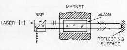
FIGURE 1: A basic optical isolator
Conoptics manufactures a family of modular Faraday rotators and interchangeable accessories which can be combined to perform various isolation functions. A basic optical isolator is shown in Figure 1. Light from a presumed well polarized laser source enters an aligned beamsplitting polarizer from the left. It then proceeds through a Faraday rotator which is tuned to 45° for the particular laser wavelength. Only one magnet is shown but, whether a single magnet or a three magnet array is used, its major field component is parallel to the optical propagation direction. Light returning from any downstream reflecting surface undergoes an additional 45° rotation in its backward pass through the glass. It is now polarized orthogonal to the forward beam and is rejected by the polarizer.
Faraday
Rotators
The Faraday rotators included in the 700
Series consist of one or more high flux NIB permanent magnets and a terbium
glass element. Tunability is accomplished by moving the glass between regions of
high and low field strength. An important feature of the Conoptics design is
that the glass does not rotate as it is moved thereby eliminating the
possibility of transmitted beam nutation due to residual wedge.
Polarization rotation is a function not only of the axial magnetic field strength, but also of the glass length, L, and its Verdet constant, V. More precisely, on axis
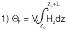
where z is along the propagation direct.
The value of V is strongly wavelength dependent and diminishes rapidly as wavelength increases. In order to avoid the need for extending the length of glass elements to achieve 45° rotation at long wavelengths, the local field strength must be increased by using combinations of magnets with opposing fields. The Model 713, 714, and 715, while outwardly quite large, have only a fraction of their lengths filled with glass. The magnet array design is intended to increase axial field strength but also affects the field radial uniformity. Only relatively small volumes along the axis of the magnet array offer sufficiently low gradients. Furthermore, tuning the rotator (changing z in equation 1) by definition means moving the glass into a region of lower integrated axial field strength and higher gradients. It is generally recommended, therefore, that for best isolation ratio, a model be chosen in which the intended operating wavelength is near the upper end of the tuning range.
A strong absorption peak at approximately 490 nm is typical of terbium glass. At wavelengths larger than 500 nm absorption is low and the models listed are capable of operation with more than 6 watts average power. Operation at 488 nm is not recommended but a special unit operable at 458 nm is available. TABLE 1 lists the specifications of standard Conoptics Faraday rotators. The isolation ratio (extinction) is dependent on the type of polarizer(s) used, the operating wavelength in relation to the tuning range, and beam diameter.
Polarizers
Figure 1 shows that it is actually the
polarizer which performs the beam separation function in an optical isolator. It
is an obvious fact that, while the homogeneity of the Faraday rotator is of
critical importance and generally limits performance in single stage devices,
the extinction of the isolator can be no better than the extinction of the
polarizer. Conoptics offers the Model 720 polarizer in two forms; one containing
a low cost, low power polarizer, the other a high performance, high power Glan
prism. Extinction as high as -40dB (10-4) is possible using the 720
Glan with a small beam and a properly tuned Faraday rotator. Extinction with the
low power type ranges between -20 and -30dB. Both types are fully rotatable.
The polarization of light reflected back towards the laser source may not be the same as that in the forward direction. Any orthogonal polarization component accidently produced will not be rejected by the polarizer-rotator combination shown in Figure 1. A second polarizer must be added to the assembly on the opposite end of the rotator and aligned at 45° to the original polarizer. This allows the forward beam to proceed with only the additional static loss of the second polarizer (<4%) but eliminates the unwanted polarization component in the backward direction. The modular design of 700 Series components provides for convenient mounting of polarizers to either end of rotator assemblies.
Quartz
Compensators
A frequently annoying feature of optical isolators
is that the polarization of the forward transmitted beam is at 45° to that of
the source. Addition of a Model 730 Compensator provides a net rotation of
either 0°or 90°, selectable by interchanging output and input ends of the
assembly. The 730's utilize the rotatory power of Z cut crystal quartz as fixed
45° elements. The effect on a transmitted polarization form is the same as that
of a Faraday rotator except it is fully reciprocal.
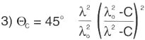
An additional advantage of the 730 is that it partially achromatizes the isolator, an important benefit when dealing with broadband or tunable lasers. A good approximation of the wavelength dependence of a Faraday rotator tuned to 45° at l0 is
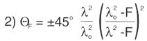
where F is a constant peculiar to the type of glass used and l0. The sense of the rotation (±) is dependent on the direction of propagation. The rotation of the 730 compensator (45°at l0) is expressed similarly,
but the sense is independent of propagation direction. The net rotation of these elements in series is
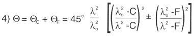
Figure 2 is an 800-1000 nm plot of equation 4 using a Model 714 Faraday rotator and Model 730 Compensator between two polarizers. In this case l0 is 880 nm. Ideal components are assumed and static losses are not shown. For the sake of comparison, an uncompensated rotator between two polarizers
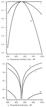
FIGURE 2: Insertion loss and extinction vs.
wavelength (nm). I, uncompensated; II, 0° rotation compensated;
III 90° rotation compensated. Models 714 and 730, l0=880nm.
Static losses are not included.
is also shown. The 714/730 combination configured to produce at 0° net forward rotation at l0 (Parallel polarizers) offers nearly lossless transmission across the wavelength band. Extinction of reflected light, however, degrades rapidly toward the band edges. On the other hand, the configuration which produces a 90° rotation at l0 in the forward direction (crossed polarizers) shows high extinction across the band with only a modest reduction of transmission towards the band edges. This means moderate wavelength changes can be made without re-adjusting the isolator. Conversion between one configuration and the other is accomplished simply by turning the entire assembly end for end and adjusting the polarizers between the crossed and parallel positions.
The Model 716
Certain lasers (e.g. diode lasers) are highly
susceptible to the disturbing influences of back reflections and the -30 to
-40dB isolation provided by Models 711A through 715 is inadequate. The Model 716
is specifically designed for such applications. Referring to Figure 3, it is
seen to consist of two Faraday elements and three polarizers. Only the carter
polarizer, P2, is rotatable about the beam axis. The Faraday elements are
identical except for the magnetic field direction reversal so that, disregarding
the effect of P2, their rotations cancel.
Assuming that forward propagating light entering P1 from the left is linearly polarized and well aligned to the transmission direction (0°) of P1, the transmission of the assembly is given by
![]()
where QF is the rotation due to each Faraday element and F is the orientation of P2. Similarly, the assembly transmission of backward propagating light is
![]()
Since the purpose of the device is to prevent back reflections, F is tuned to make TB = 0, that is, QF + F = 90°. Substituting in Equation 5,
![]()
Equation 2 shows how QF varies with deviations from the peak wavelength, l0. Equation 7 shows that as QF varies from 45° and F is tuned to maintain high backward extinction, the forward transmission is reduced. Figure 4 is a plot of the forward transmission of Model 716 as the center polarizer is rotated for best backward extinction at wavelengths near the peak wavelength of 823 nm. Since the 716 is supplied complete with three polarizers, all static losses are included. The peak wavelength of Model 716 can be factory adjusted to any wavelength within the range 600 to 850 nm.
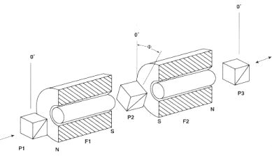
FIGURE 3: Model 716 internal construction. P1, P2,
and P3 are polarizers; F1 and F2 are Faraday rotators.
Equations 6 and 7 represent ideal components. In general, however, the residual imperfections of both Faraday rotators and polarizers limit extinction of back reflected light. The tandem configuration of the Model 716 effectively halves the leakage (in dB) due to radial field gradients and glass imperfections in the Faraday elements thereby making extinction of the polarizers the limiting factor. A crossed pair of Conoptics Glan polarizers exhibits an extinction of approximately -60dB (a transmission ratio of 10-6). The residual leakage is caused by surface and bulk scattering and spurious birefringence. On average, the leakage can be considered to be unpolarized and the third polarizer adds only another -3dB to the extinction. Careful manufacturing and selection procedures assure that an extinction of at least -60dB can be achieved and maintained with the Model 716.
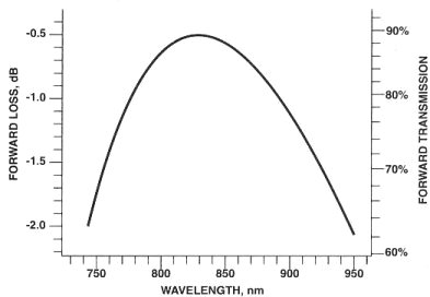
FIGURE 4: Forward transmission as a function of
wavelength for best isolation for a Model 716 peaked at 823nm
(-1dB range is 110nm centered at 830nm). All static losses are included.
Table 1
| MODEL | 711A | 712A | 713 | 714 | 715 | 716 |
| Tuning Range (1), nm | 500-645 | 585-750 | 725-870 | 685-990 | 965-1135 | ±6.5% l0(2) |
| Clear Aperture, nm | 5.0 | 5.0 | 5.0 | 5.0 | 5.0 | 5.0 |
| Insertion Loss (3) | -.04dB | -.04dB | -.04dB | -.09dB | -.09dB | -.5dB |
| Extinction (4) | -40dB | -40dB | -40dB | -37dB | -37dB | -60dB |
Notes to the Table:
(1) Due to lot variations in magnets and glass, the values given are
approximate.
(2) The peak wavelength (600-850 nm) must be specified when ordering.
(3) Includes three Glan polarizers at the peak wavelength for Model 716; all
others without polarizers.
(4) With Model 720 Glen polarizers.
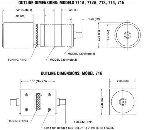
Notes to the Drawing:
(1) Dimension "A" = 2.80 (71) for Models 711A and 712A; "A"
= 4.95 (126) for Models 713, 714 and 715.
(2) Models 720 and 730 are optional and may be mounted on either end of the
Faraday rotator.
(3) Dimension "B" = 3.23 (62) for a Model 716 peaked at 823 nm.
"B" increases with decreasing wavelength.
Peak wavelength must be specified when ordering.

Home | Prodotti | Lista rappresentate | Modulo Informazioni | News | Contatti